When designing a zero energy home (ZEH), you’ll need to pay attention to several concepts that don’t usually come up when working on more conventional buildings. One such concept involves being clear about what parts of the building are inside and which are outside. Sounds simple doesn’t it?
Please think again. Insulation and air sealing are key components of a successful zero energy building envelope, so keeping the inside and the outside straight is crucial and a bit complex.
A building envelope serves several important functions. It keeps weather out. It keeps heat in. It blocks drafts. It resists decay. It’s best if all four of these functions happen in the same plane. An exterior wall offers a straight-forward example. Siding and housewrap on the outside block wind and rain. Insulation resists heat movement. Caulk and expanding foam seal air leaks. Vapor retarders inhibit moisture transmission and resulting decay. Interior drywall covers the cavity and provides additional air sealing. All this happens in the depth of just a few inches.
But what about the attic? Is it inside or outside? It’s “inside” from the weather but “outside” of the temperature-controlled comfort zone. Similar questions arise with crawlspaces, garages, vestibules, forced-air ducts, bump-outs and some storage rooms and other more complicated architectural details. These issues can best be managed by a few simple strategies.
Heat loss and air leakage occur from the building’s thermal envelope–the shell. Architecturally complex buildings increase surface area. More important, they are difficult to effectively insulate and air seal. I’m not suggesting we all live in cubes. However, outside corners, multiple roof pitches and odd framing enclosures just make it more difficult to reach the goal of super energy efficiency. So if there is not a clear benefit to complexity, keep it simple.
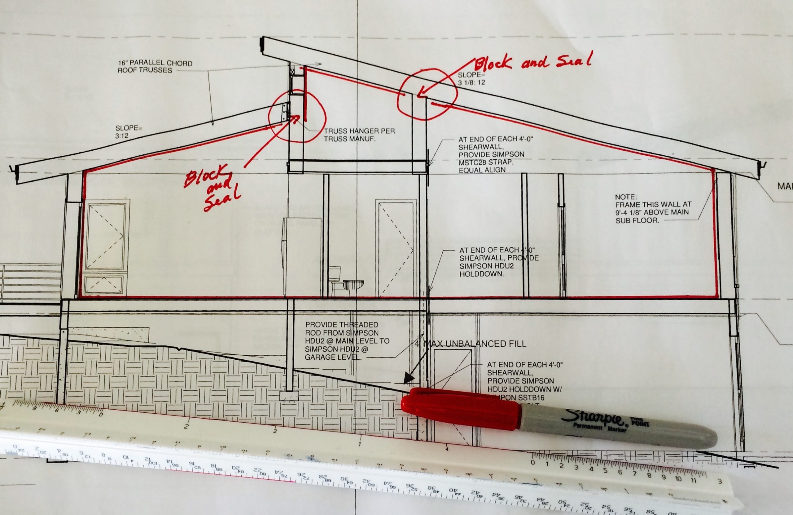
Designers should have a very clear idea of exactly where the thermal boundary is. Try this trick. Use a red pencil to trace the insulated shell of the building on a set of paper drawings. Do this on the plan view of each level and on every cross section. The pencil should never leave the paper until it reaches the spot where it began. This red line should be the location of the air barrier and insulation layer. If you have to lift the pencil, you’ve found a gap that demands attention.
Insulation should occupy the space just inside this 6-sided box. Again, a typical wall is a good example. Here the box comprises two studs, a top plate, a bottom plate, drywall on the inside surface and sheathing on the outside surface. This part of the box is filled with insulation and air sealed. Easy enough.
Unfortunately, modern designs are riddled with ambiguous spaces. If the attic space is outside, what happens at the insulated wall between attic space and a room with a cathedral ceiling? If you looked at that wall from behind you would see naked insulation. Not good. Cold attic air will wash through the exposed insulation, reducing its effectiveness. Also, any crack or hole in the drywall will allow inside air to stream into the attic. This wall needs to be covered and sealed on the cold side, too. Generally, OSB is used for this “backing” material, although any rigid sheet material will do.
Now think about all the other places that need backing and air sealing. Behind tubs and showers. Behind fireplaces. At the top of any soffit or chase. Attic knee walls.
One builder I know was caught completely off guard by a home design that included an attic space behind a knee wall. The roof framing was a set of trusses the entire length of the building. It was an elegant structural element that allowed a bank of south-facing clerestory windows lighting a long, high hallway. However, the entire north side was an unheated attic with an insulated wall opposite the clerestories. Roughly 50 feet of attic wall needed backing and air sealing to cover wall insulation facing the attic space. Numerous truss members which crossed that side of the attic wall made for an excruciating job of cutting and fitting the backing material. And even when it was done, the air leakage rate of was far higher than anyone wanted.
How could this have been avoided? At the design stage, it could have been decided to continue the thermal boundary along the roof plane all the way to the north side of the building and then down the outside wall. Following the exterior surfaces, insulating and air sealing would have been far easier and less expensive. This would have brought the long attic space inside the thermal boundary. It would have been a great location for mechanical equipment, such as the heat recovery ventilator and ductwork.
Design is the time to think about the location of the thermal boundary. Always place the air barrier and insulation in the same plane. Keep the architecture simple and use your red pencil. Following these principles will simplify the road to zero energy success.
—Bruce Sullivan, Building Science Consultant, www.basezero.biz


David Esau says:
Interesting article. But the picture illustrating it does not show the red boundary where the article says it should be!